ADC Pi
-
Raktár 1:
5 db
-
Raktár 2:
0 db
- Cikkszám 57126
-
-


akár 1 órán belül
Termékfülek
Leírás
ADC Pi
Features
- 8 x 17-bit 0 to 5V Single Ended Inputs
- Control via the Raspberry Pi I2C port
- Stack up to 4 ADC Pi boards on a single Raspberry Pi
- Jumper selectable I2C addresses
- Buffered 5V I2C port
- Based on the MCP3424 from Microchip Technologies Inc
- Single Ended full-scale range of 5.0V
- On-board 2.048V reference voltage (Accuracy ± 0.05%, Drift: 15 ppm/°C)
- On-Board Programmable Gain Amplifier (PGA): Gains of 1, 2, 4 or 8
- Programmable Data Rate Options:
- 3.75 SPS (17 bits)
- 15 SPS (15 bits)
- 60 SPS (13 bits)
- 240 SPS (11 bits) - One-Shot or Continuous Conversion Options
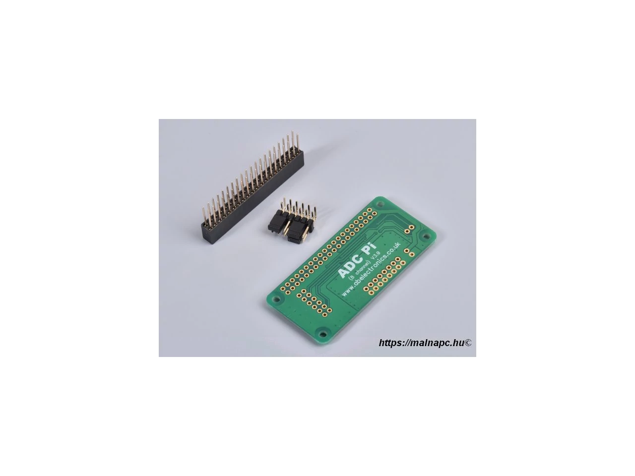
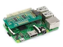
The ADC Pi is an 8 channel 17 bit analogue to digital converter designed to work with the Raspberry Pi. The ADC Pi is based on two Microchip MCP3424 A/D converters each containing 4 analogue inputs. The MCP3424 is a delta-sigma A/D converter with low noise differential inputs.
Not sure which ADC you need ? Check our Analogue to Digital Buyers guide to compare our ADC expansion boards.
We designed the ADC Pi to work as a single ended A/D converter using the internal 2.048V reference voltage with the -V pins tied to ground. A voltage divider on the ADC Pi board brings the input voltage range to a much more useful 0 – 5.06V. In this configuration the sample size is 17 bits for each channel.
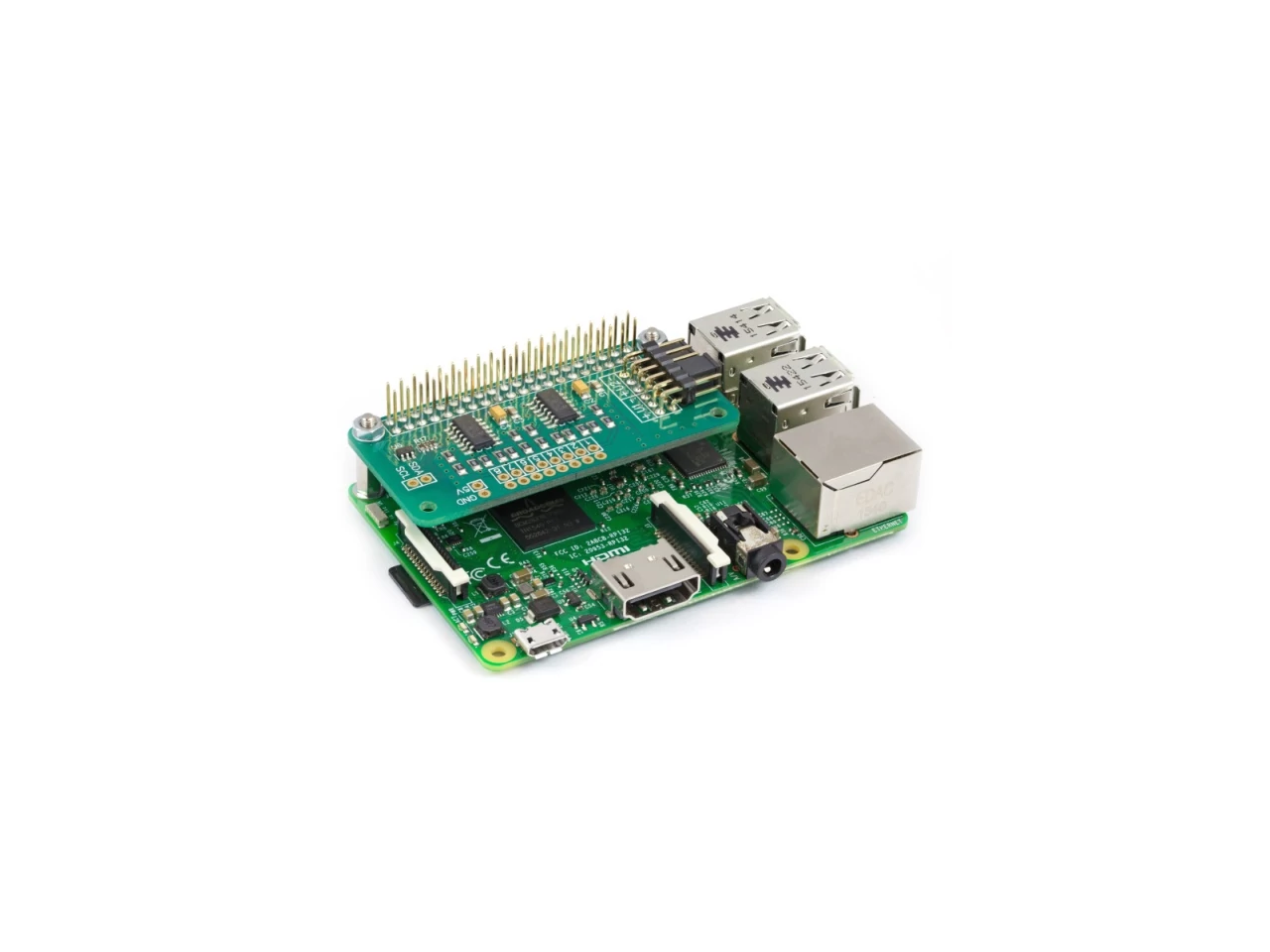
The ADC Pi is powered through the host Raspberry Pi using the GPIO port and extended pins on the GPIO connector allow you to stack the ADC Pi along with other expansion boards.
The two MCP3424 A/D converters communicate via i2c to the host Raspberry Pi giving you eight analogue inputs to use. A logic level converter is included on the ADC Pi board giving you a buffered 5V i2c port making it easy to add other I2C devices which operate at 5 volts without damaging the raspberry pi 3.3 volt i2c port. The i2c buffer uses N-channel mosfets with a maximum drain current of 100mA.
The I2C address bits are selectable using the on-board jumpers. The MCP3424 supports up to 8 different I2C addresses so with two A/D converters on each ADC Pi you can stack up to 4 ADC Pi boards on a single Raspberry Pi giving you 32 ADC inputs.
The MCP3424 contains a programmable Gain Amplifier giving the user a selectable gain of x1, x2, x4 or x8 before the analogue to digital conversion takes place.
The data rate for analogue to digital conversions is 3.75 (17 bit), 15 (15 bit), 60 (13 bit) or 240 (11 bit) samples per second. Data rate and resolution can be configured within software using the I2C interface.
We have a knowledge base article, ADC Sample Rate Comparison which has more detailed sample information and test scripts to compare the different MCP2424 ADC chip bit and sample rates.
Unused inputs should be tied to ground.
If you want to sample a higher input voltage you can use our ADC Pi Input Voltage Calculator to find the additional resistors and calculation values needed.
Specifications
Input Ratings & Specifications
| Spec | Ratings |
| Vdd (5V pin on I2C bus) | 5.0V |
| ADC Input Voltage | 0V to +5.06V |
| Maximum ADC Input voltage | VSS–0.4V to VDD+0.4 V |
| Current at Input Pins | ±2 mA |
| I2C SDA/SCL voltage | 5.0 V |
| I2C port current | 100 mA |
3D CAD Model
![]() ADC Pi - 3D CAD File (STEP Format)
ADC Pi - 3D CAD File (STEP Format)
Board Layout

Schematic

Click to download schematic PDF.
Mechanical Drawings

Assembly
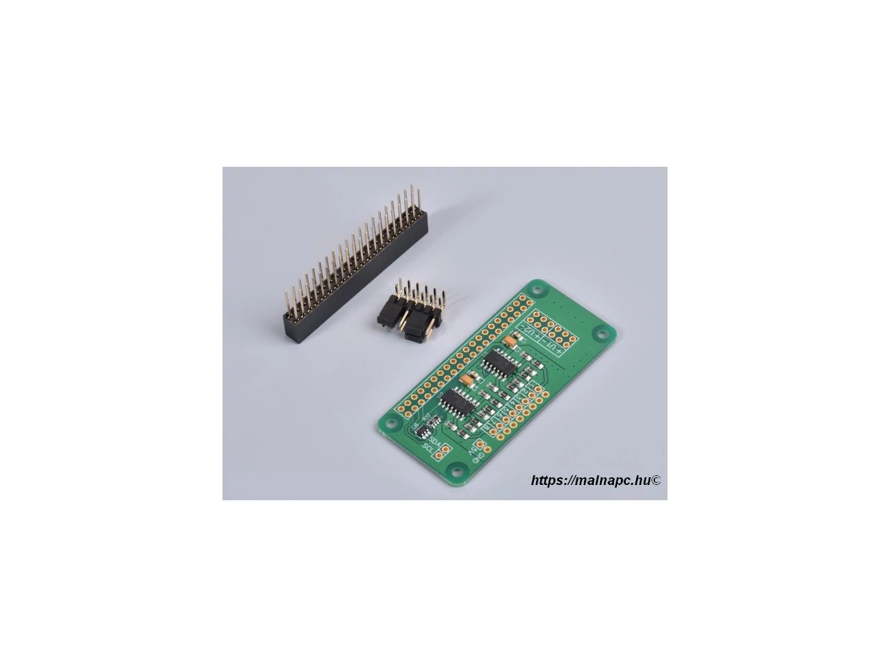
The ADC Pi is supplied with the 40 pin GPIO connector and the 12 pin address connector unsoldered. We supply the ADC Pi this way because the Raspberry Pi Zero is also supplied without a GPIO header and the ADC Pi could therefore be fitted both above or below the Raspberry Pi Zero.
Before using the ADC Pi you will need to solder both connectors onto the PCB. We suggest soldering the 40 pin GPIO connector first and then the address select connector. Soldering the address select connector first will make it difficult to access the three corner pins on the GPIO connector.
![]()
The assembly video for the ADC Pi Plus shows the same steps that are needed to assemble the ADC Pi .
PCB Header Assembly Jig
Download and print our PCB Header Assembly Jig to hold your circuit board when soldering the header pins.
I2C Address Table
| Adr 0 | Adr 1 | I2C Address |
| Low or Float | Low or Float | 0x68 |
| Low | Float | 0x69 |
| Low | High | 0x6A |
| Float | Low | 0x6B |
| High | Low | 0x6C |
| High | Float | 0x6D |
| High | High | 0x6E |
| Float | High | 0x6F |
The MCP3424 analogue to digital converter contains two address select pins which can be tied to Vss, Vdd or left floating. This gives 8 possible I2C addresses for each chip. The ADC Pi contains two MCP3424 chips so you can stack up to 4 The ADC Pi boards on a single Raspberry Pi. To simplify address selection on the The ADC Pi we have included a set of address selection pins which can be configured using the included jumpers. The illustrations below show the four recommended configurations for your The ADC Pi and the associated I2C addresses.
Note:
Disconnect the The ADC Pi from the Raspberry Pi before changing the address pins. You may need to short the 5V and ground with a resistor to discharge the capacitors in order for the new addresses to be recognised.

Warning
Do not under any circumstanced connect the two centre pins together. This will create a direct short between the 5V and ground pins and will damage or destroy your Raspberry Pi and ADC Pi Plus board.

I2C Address Table
Recommended Address Configurations
Configuration 1:
Analogue Channels 1-4 = I2C Address: 0x68
Analogue Channels 5-8 = I2C Address: 0x69

Configuration 2:
Analogue Channels 1-4 = I2C Address: 0x6A
Analogue Channels 5-8 = I2C Address: 0x6B

Configuration 3:
Analogue Channels 1-4 = I2C Address: 0x6C
Analogue Channels 5-8 = I2C Address: 0x6D

Configuration 4:
Analogue Channels 1-4 = I2C Address: 0x6E
Analogue Channels 5-8 = I2C Address: 0x6F

Compatibility
| Model | Status |
| Raspberry Pi Model A |
|
| Raspberry Pi Model B |
|
| Raspberry Pi 1 Model A+ |
|
| Raspberry Pi 1 Model B+ |
|
| Raspberry Pi 2 Model B |
|
| Raspberry Pi 3 Model B |
|
| Raspberry Pi 4 |
|
| Raspberry Pi Zero |
|
| Raspberry Pi Zero W |
|
| Orange Pi |
|
| Asus Tinker Board |
|
| Odroid |
|
Ajánlott termékeink