IO Pi Plus
- Gyártó AB Electronics UK
-
Raktár 1:
0 db
-
Raktár 2:
0 db
- Cikkszám 37014
-
-


akár 1 órán belül
Termékfülek
Leírás
Features
- 32 Digital Inputs/Outputs
- Control via the Raspberry Pi I2C port
- Stack up to 4 IO Pi boards on a single Raspberry Pi
- Solder jumper selectable I2C addresses
- External 5V Input with isolation solder jumper
- Based on the MCP23017 from Microchip Technologies Inc
- Configurable interrupt output pins - Configurable as active-high, active-low or open-drain
- INTA and INTB can be configured to operate independently or together
- Configurable interrupt source - Interrupt-on-change from configured register defaults or pin changes
- Polarity Inversion register to configure the polarity of the input port data
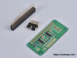
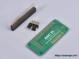
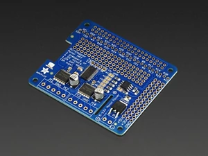
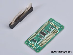
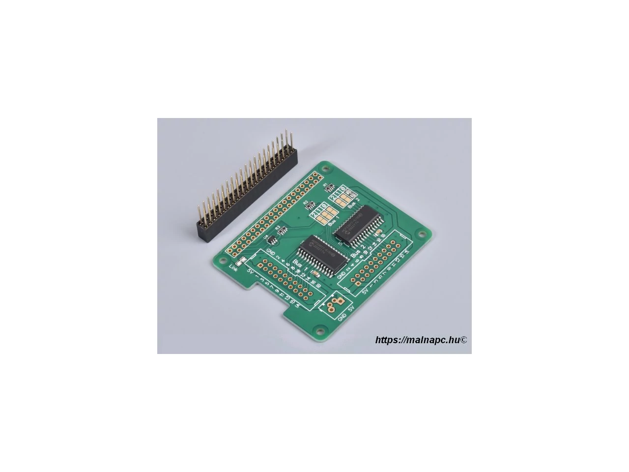
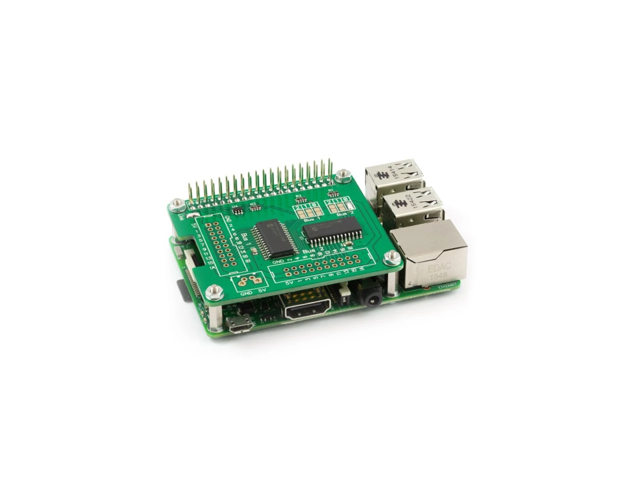
The IO Pi Plus is a 32 channel digital expansion board designed for use on the Raspberry Pi. The board is based around the MCP23017 16-bit I/O expander from Microchip Technology Inc. A pair of MCP23017 expanders are included on the board allowing you to connect up to 32 digital inputs or outputs to the Raspberry Pi. The IO Pi Plus is powered through the host Raspberry Pi using the GPIO port and extended pins on the GPIO connector allow you to stack the IO Pi Plus along with other expansion boards.
The I2C address bits are selectable using the on-board solder jumpers. The MCP23017 supports up to 8 different I2C addresses so with two MCP23017 devices on each IO Pi you can stack up to 4 IO Pi boards on a single Raspberry Pi giving a maximum of 128 I/O ports.
The IO Pi Plus includes a 5V port that can be isolated from the Raspberry Pi via an isolation solder jumper marked "Link" on the PCB so you can use a separate high current power supply to power the IO Pi reducing the load on the Raspberry Pi. Use of an external supply is recommended if you plan on connecting more than one IO Pi Plus to your Raspberry Pi. The 5V input is compatible with our 5mm screw terminals.
To use the IO Pi Plus externally from the Raspberry Pi you will need to connect the 3.3V (Pin 1), SDA (Pin 3), SCL (Pin 5) and Ground (Pin 6) pins from the Raspberry Pi GPIO header to the corresponding pins on the IO Pi Plus. The 5V pin will also need to be connected if you are not using an external 5V power supply.
Legacy IO Pi Versions
See our KB article for previous versions of this board.
Specifications
Input Ratings & Specifications
| Spec | Ratings |
| Vdd (5V pin on I2C bus) | 2.7V - 5.5V |
| All digital inputs and outputs: | 0 - Vdd |
| Current at I/O Pin (sourced or sunk): | 25 mA |
| Maximum current on a single I/O Bank (1 MCP23017 device): | 125 mA |
3D CAD Model
![]() IO Pi Plus - 3D CAD File (STEP Format)
IO Pi Plus - 3D CAD File (STEP Format)
Schematic

Click to download schematic PDF.

Assembly
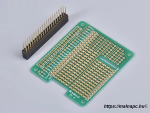
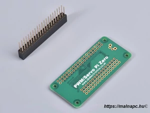
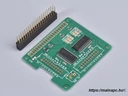
The IO Pi Plus is supplied with the 40 pin GPIO connector unsoldered. Before using the IO Pi Plus you will need to solder the connector onto the PCB. The power link and I2C address selection are configured using solder jumpers. For your convenience we supply the IO Pi Plus with the power link jumper and one address selection jumper pre-soldered.
The digital input pads are spaced 2.54mm apart. You can solder wires directly to the board or use 2.54mm pitch headers. The IO Pi Plus is compatible with 20 pin IDC vertical and right angle headers allowing you to use ribbon cables to connect your external devices to the board.
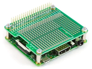
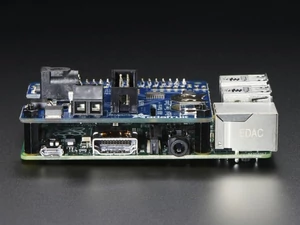
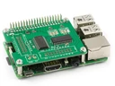
To install the IO Pi simply press the 40 pin connector down onto the Raspberry Pi GPIO pins with the board sat over the top of the Raspberry Pi.
If you are installing more than one IO Pi on a single Raspberry Pi board then you will need to configure the address select jumpers for each IO Pi.
Remove the isolation jumper when connecting an external power supply to the 5V port.
PCB Header Assembly Jig
Download and print our PCB Header Assembly Jig to hold your circuit board when soldering the header pins.
![]()
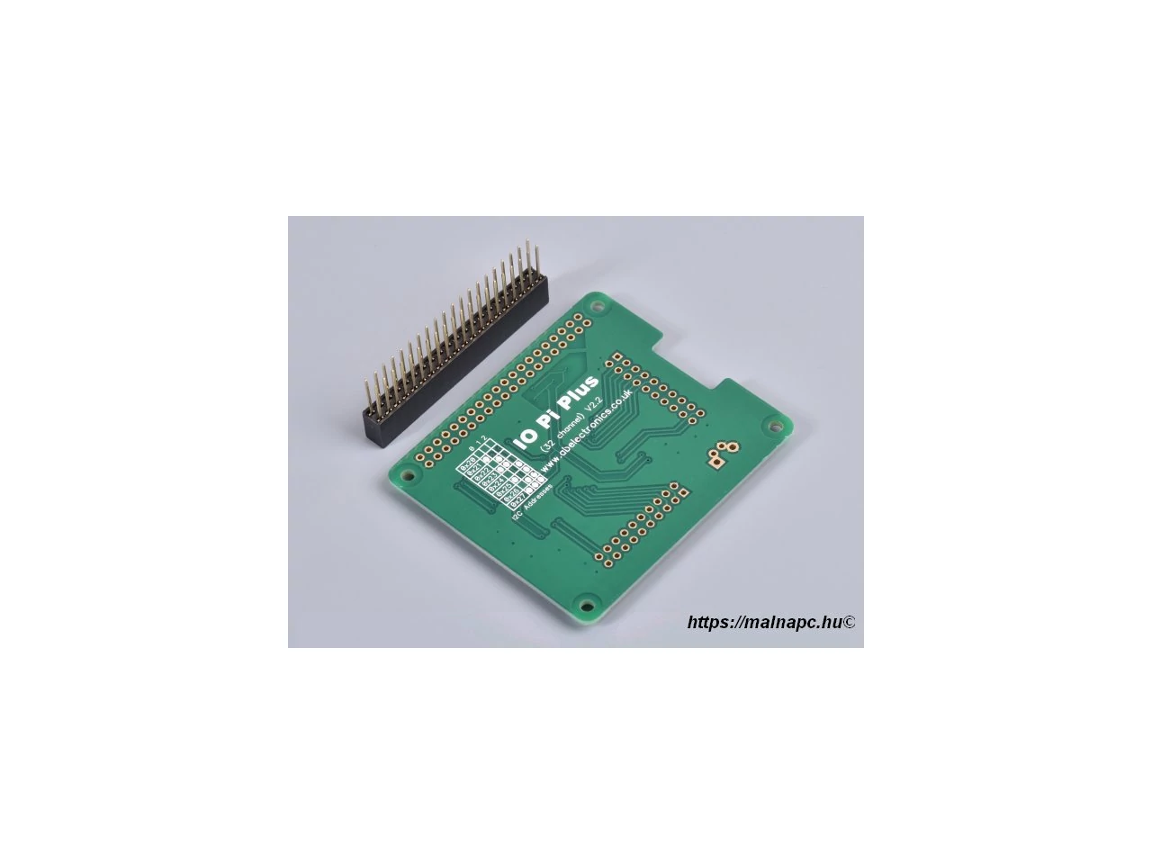
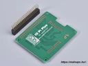
The MCP23017 contains three address select pins which can be tied to Vss or Vdd. This gives 8 possible I2C addresses for each chip. To simplify address selection on the IO Pi Plus we have included a set of address selection pads which can be configured by applying a small solder bridge across the required pads. The I2C address table show the recommended configurations for your IO Pi Plus and the associated I2C addresses.
Note:
Disconnect the IO Pi Plus from the Raspberry Pi before changing the i2c address. The address pins are tied to GND (low) via a 10K resistor so the jumper is used to tie a pin to Vcc (high).
Default Configuration (IC1 = 0x20, IC2 = 0x21)
I2C Address Table
| 2 | 1 | 0 | Adress |
| - | - | - | 0x20 |
| - | - |
|
0x21 |
| - |
|
- | 0x22 |
| - |
|
|
0x23 |
|
|
- | - | 0x24 |
|
|
- |
|
0x25 |
|
|
|
- | 0x26 |
|
|
|
|
0x27 |
Compatibility
| Model | Status |
| Raspberry Pi Model A |
|
| Raspberry Pi Model B |
|
| Raspberry Pi 1 Model A+ |
|
| Raspberry Pi 1 Model B+ |
|
| Raspberry Pi 2 Model B |
|
| Raspberry Pi 3 Model B & 3+ |
|
| Raspberry Pi 4 |
|
| Raspberry Pi Zero |
|
| Raspberry Pi Zero W |
|
| Orange Pi |
|
| Asus Tinker Board |
|
| Odroid |
|
Ajánlott termékeink